CONSTRUCTION
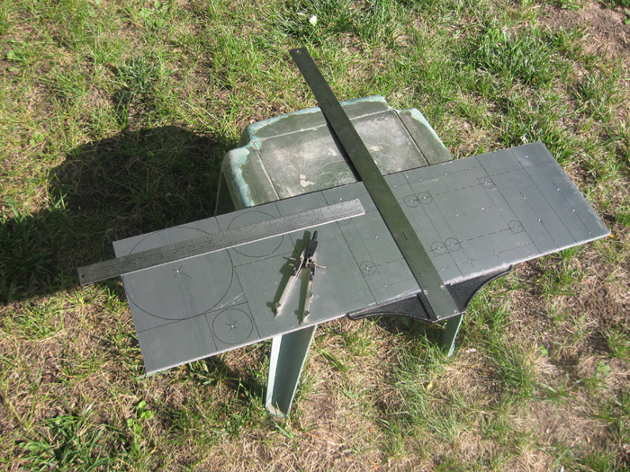
My first prototype was not an epic fail, nor was it an amazing success. So I found more 1/4" aluminum plate, this time from a local source. I went back to the drawing board and redesigned the tripod mount to accomodate the surveyor's tripod, and beefed up the end mounts, doubling the distance between the arms from 2" to 4". The above photo shows the new parts carefully drawn on the sheet of aluminum plate.

Holes to be drilled are marked with a center punch. Those 1" circles are for inside corners. Inside corners are hard to cut with a bandsaw, so I drill out the corner with a 1" spade bit and you end up with a nice rounded inside corner.

Here are the parts cut out from the sheet.
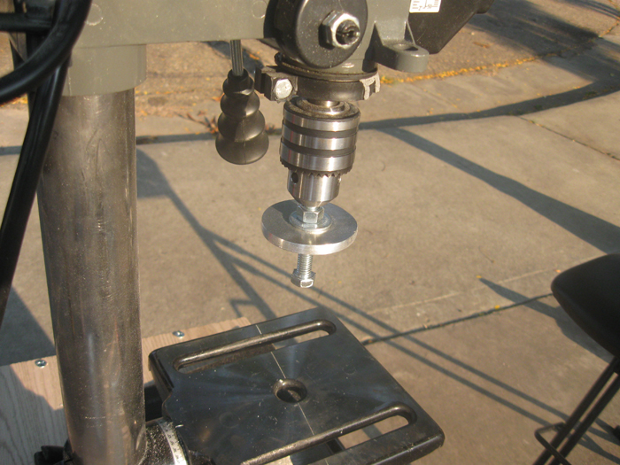
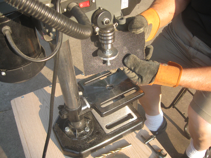
The rough cut circular plates are mounted in the drill press and rounded smooth with emery cloth.
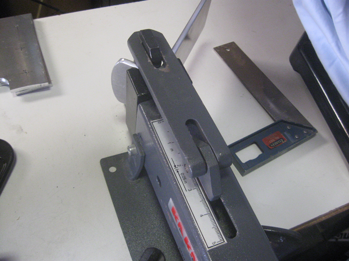
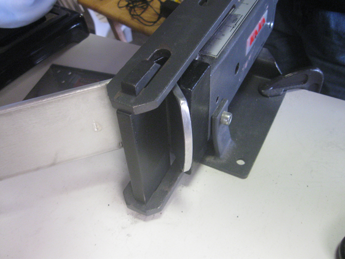
Here are two views of the metal bender bending one of the upright center pivot brackets.
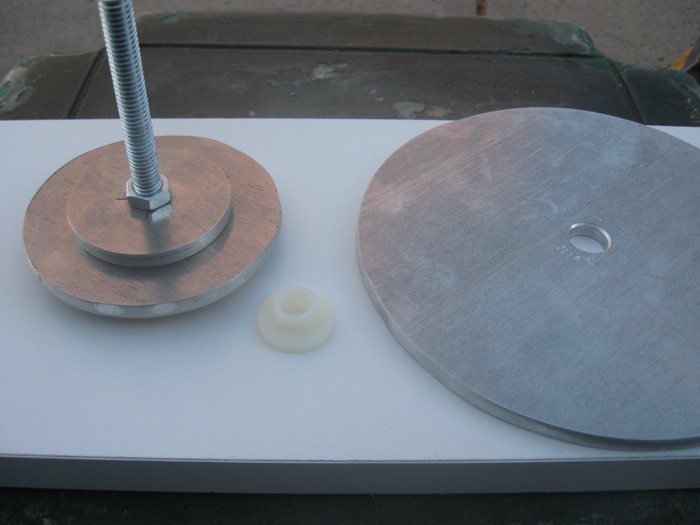
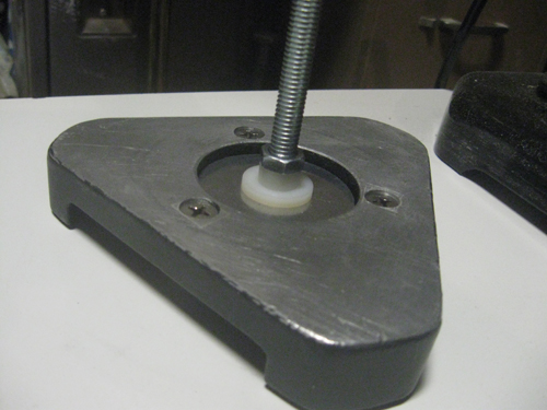
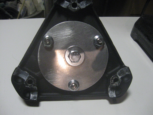
These are the three round plates needed to secure the center pivot bolt to the tripod. In the middle is a nylon shoulder bushing. It fits in the center hole of the large top plate and provides a bearing surface between the top plate and center pivot bolt.

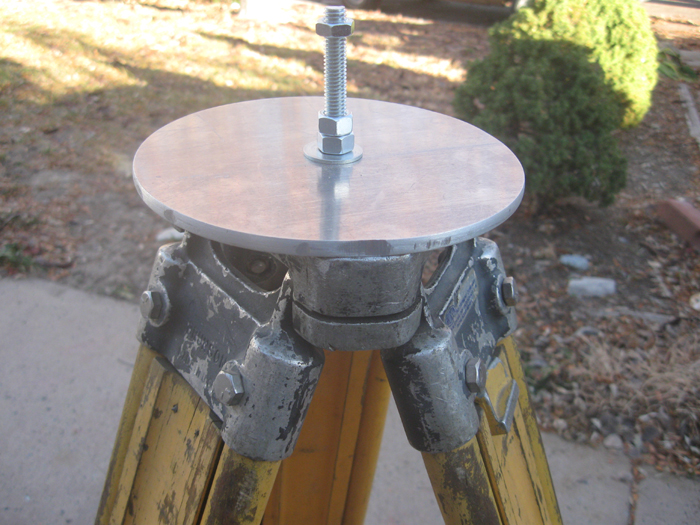
Bottom plate assembly and tripod head
Bottom plate assembly underneath tripod--tripod turned upside down.
The bottom plate assembly fitted into upside-down tripod
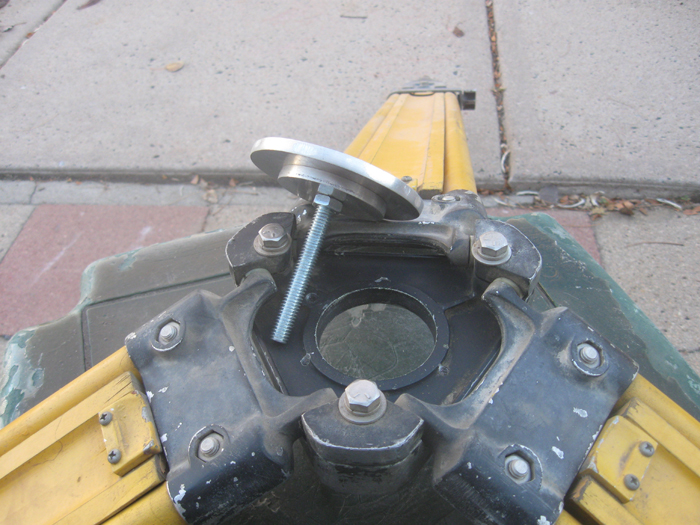
The bottom plate assembly coming up from underneath the tripod head. The smaller disc on top of the bottom plate fits just inside the center hole in the tripod head. It functions to help maintain the lateral stability of the center pivot bolt.
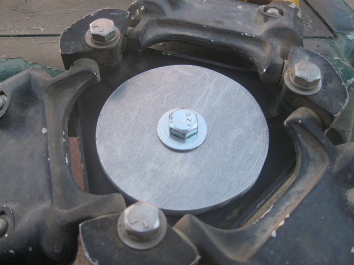
Bottom plate assembly set in place in tripod head
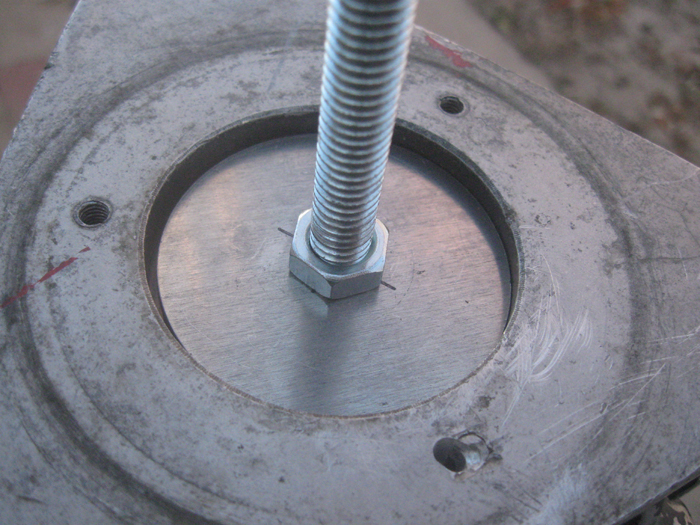
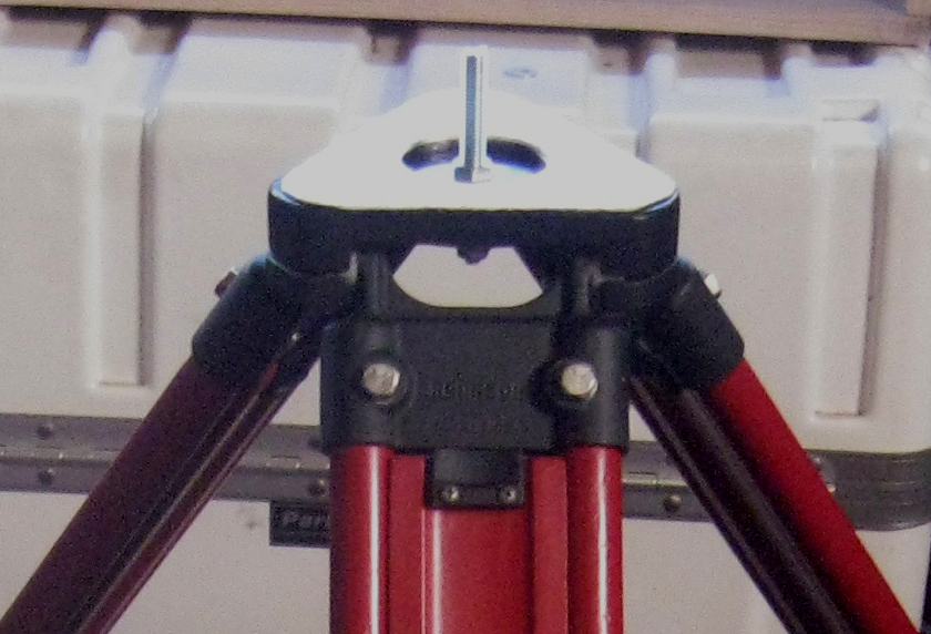
The top plate set in place on the tripod head, test fit.
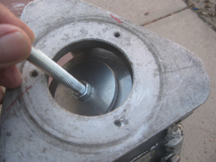
Tripod head top view with center pivot bolt mounted.
Tripod head bottom view with bottom backing plate and center pivot bolt in place.
The reassembled tripod head with the textured RPF (similar to Formica) bearing plated cemented inplace.
Go to tripod modification page for more details on tripod.
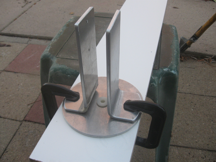
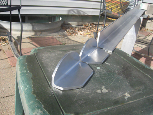
Center pivot mockup. Uprights clamped to top plate. This design was abandoned in favor of this:
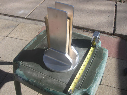
This is the mockup of the redesigned center pivot bracket assembly. It is several inches taller than the original prototype to accomodate a third beam and allow greater degree of downward movement. Perhaps the most important change is that I abandoned trying to fabricate the uprights using the metal bender. It was impossible to get a good straight 90 degree bend and have all of the mounting holes line up correctly. Instead I substituted 90 degree brackets that I fabricated from 2-1/2" x 2-1/2" x 1/4" extruded aluminum angle stock:
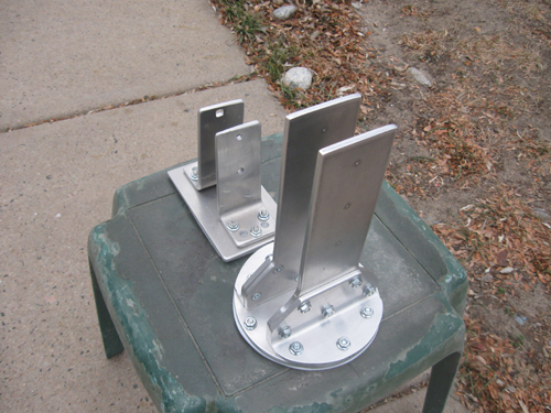
Here is the assembled new version of the center pivot bracket assembly, compared to the version 2 prototype. The V2 prototype was assembled and tested. It worked fairly well, but still wasn't the rock steady mount that I was after. I gave it a try out at our club's dark sky site in January, and it performed quite well. This was my first opportunity to use the big Orion 25x100 binoculars with a nice steady mount, and they were great. I observed about a dozen Messier objects, mostly open clusters this time of year. The Orion Nebula was fantastic at this magnification and aperture, the tiny stars of the Trapezium popping right out. The Bode's nebulae, M81 and M82, were also spectacular revealing far more detail than my smaller binoculars.
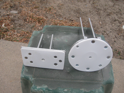
Bottom view of both versions of the pivot assemblies showing PTFE (Teflon) bearing plate. The mounting screws are 1/4" flat head machine screws and the mounting holes are countersunk into the PTFE sheet.
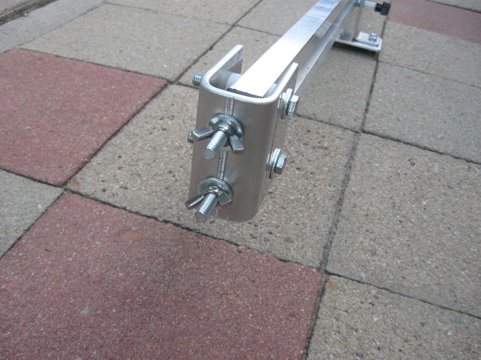
Prototype p-end. This part has been redesigned and is being refabricated. I included these obsolete images to illustrate the nylon bushing connection between the p-end and the beams
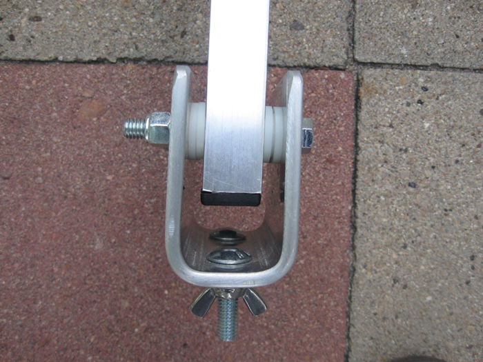
Notice that the ends of the beams are closed off with black plastic caps (available online) to seal out moisture.
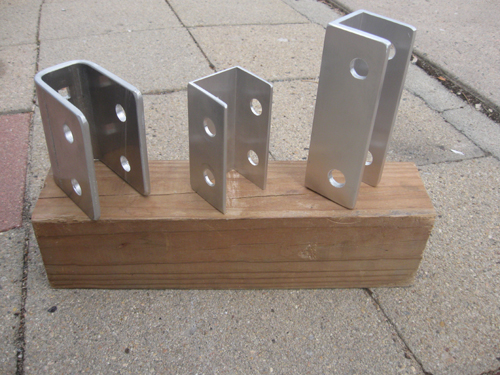
This photo illustrates the evolution of the p-end bracket. On the left is the original bracket shown in the photos above. It was fabricated from 1/4" aluminum plate and bent into shape with the metal bender. The bender did not perform well. It was impossible to make precise bends. The result is that the drilled holes did not line up perfectly and there was a lot of binding in the completed version 1 prototype.
The center bracket was a temporary fix. It is constructed form 1/8" thick 2" x 2" extruded aluminum channel that I had on hand. This worked much better, and I used it to assemble version 2 prototype which worked much better.
On the right is the final version of the p-end bracket, constructed from 1/4" x 2" x2" extruded aluminum channel. I could not source this material locally and had to order it from an online source (onlinemetals.com). Note that the center bracket is much taller than the earlier two versions. This is because I made a major revision, adding a third beam for addtional strength and stability.
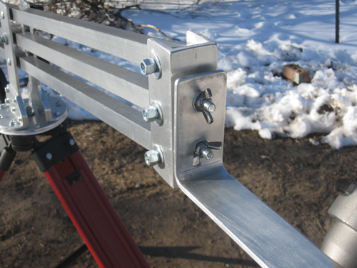
Here is the completed and assembled p-end bracket. This end of the mount is intented to support a larger binocular, and all three of the beams extend to the p-end bracket. On the other end, the three beams only extend to the counterweight assembly, and the upper and lower beams extend the the p-end bracket on the other end, designed to support a lighter binocular.
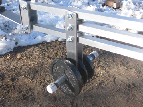
Here is the couterweight assembly. In the prototype versions 1 and 2, the counterweight only had one point of attachment on the lowermost beam. In the redesigned triple beam version, the counterweight is suspended from all three beams. This distributes the load of the couterweight to all three beams rather than just the lowermost beam. It also generates three more points of contact in the parallelogram structure, adding to the overall stability.
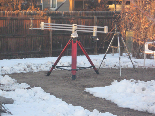
Long view of completed Binocrane parallelogram mount. The second tripod in this view is used as a support during assembly.
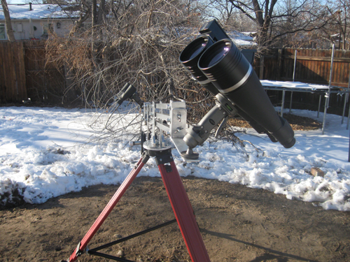
The completed parallelogram mount with 25x100 Orion Giantview binoculars on a Dolica trigger ball mount on the close end. The far end is holding a pair of Nikon Aculon 7x35 binoculars.